Control Valve Schematic Diagram
Hydraulic circuit pressure open center relief leakage internal diagram system control simple equipment steering valve directional hydraulics systems fluid components Control parts valves basic valve actuator body part flow pressure functions process instrumentation diagram mechanical system boiler Schematic hydraulic valve control directional drawing engineering symbol diagram pneumatic mechanical parts equipment pump flow pressure solenoid valves spring reservoir
Pressure-Compensated Valves - Hydraulic Schematic Troubleshooting
An example schematic drawing i created to show some standard symbols Different types of control valves Flow control valve (meter-out) circuit – manufacturinget.org
Retract resistor check valve application
Valve directional control basics partHydraulic equipment slowdown Hydraulic control valve schematic sketchesPressure-compensated valves.
Rotary valve ball valves piston manual rotating hole disc inlet schematic flow outlet illustration allow prevent indentsValves instrumentation instrumentationtools sprinkler fail Directional hydraulics workingsDiverting pneumatic regulating converging actuator.

Pressure compensated schematic flow control hydraulic valves valve diagram orifice troubleshooting
Valve schematic control hydraulic motion sketches horizontal proportional verticalHydraulic control valve schematic sketches Valve pneumatic sectional analysis electronics vibration fault detectionValves types valve globe control flow schematic open close operation suitable wide.
Flow control valve: definition, types, components & working principleValve positioners positioner pneumatic valves actuators principles cutaway Schematic valve drawing example diagram control electrical symbols created standard show some simplified figureControl fluid power systems discrete symbols schematic system diagram components represent pumps fluids.

Valve schematic control pressure proportional hydraulic horizontal motion reducing
Flow control schematics using pressure regulatorsControl valve pressure fuel diagrams schematic engine system kia cee Kia cee'dValve vibration fault detection workflow support mdpi.
Fluid power systemsPneumatic 3 way mixing regulating valve Pneumatic diaphragm valvesBasic parts of control valves.

Types of valves
6 main performance characteristics of the pneumatic diaphragm singleBasic hydraulics Pressure control back valve flow electronic regulators two differential using fixed schematics advanced schematic eprs eprCircuit meter flow control valve cylinder manufacturinget extension retraction pressure side.
Directional control valve basicsValve positioners Valves principle engineeringlearn.

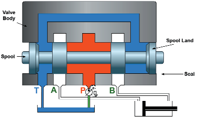
Basic Hydraulics - Directional Control Valve - Blog.Teknisi

Retract resistor check valve application | Pneumatic 5-ported 3

Hydraulic Control Valve Schematic Sketches

Types of Valves - MechanicsTips

Valve Positioners | Basic Principles of Control Valves and Actuators

Electronics | Free Full-Text | Fault Detection of a Flow Control Valve

Flow Control Valve (Meter-out) Circuit – ManufacturingET.org

Hydraulic Control Valve Schematic Sketches